
| Home |
| Mechanics |
| Thermo-Mechanics |
| Micro- and Nano Mechanics |
| Computational Fluid Dynamics |
| Acoustics |
| Multi-Physics |
| Physics of Failure, Reliability and Durability |
| Electronic Reliability |
| URAY |
| Architectural and Building Acoustics |
| Contact |
| Job Openings |
| GDPR-Privacy |
| Udy VOF Kapellestraat 64 9220 Hamme Belgium RPR Dendermonde 474005247 BTW 0474005247 T +32 (0)52472733 M +32 (0)498624767 E info@Udy.be |
Integrated PCB Electronics Reliability and Thermal Management of Electronic Systems
Udy performs integrated reliability test and thermal management simulations of PCB (Printed Circuit Board) or PBA (Printed Board Assembly) for the purpose of revealing and correcting design faults from the beginning
See below for some examples from our portfolio. Each slide represents one successfully accomplished customer project
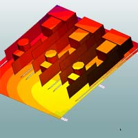
- Cooling fins for PCB in electronic enclosure
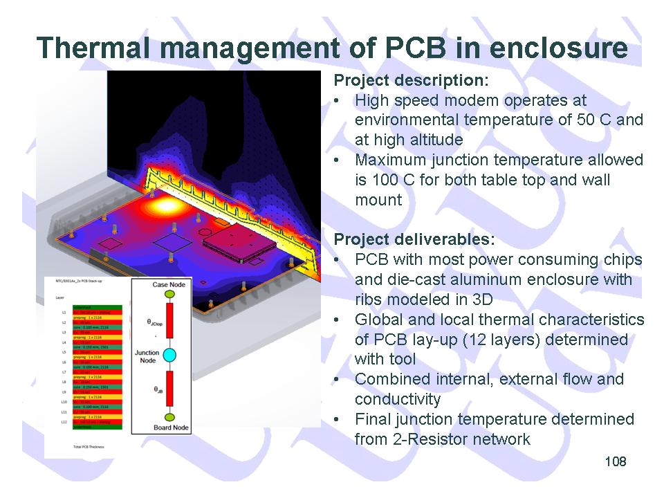
- Thermal management of PCB in enclosure
- Reliability of electronic device
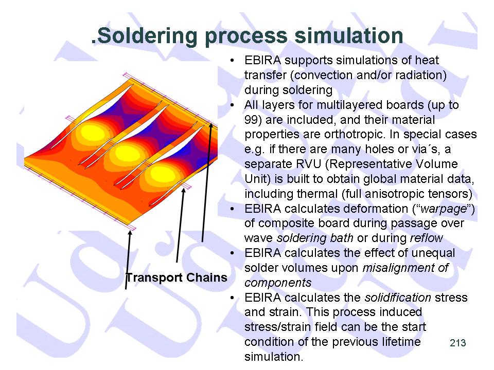
- Solderin process simulation
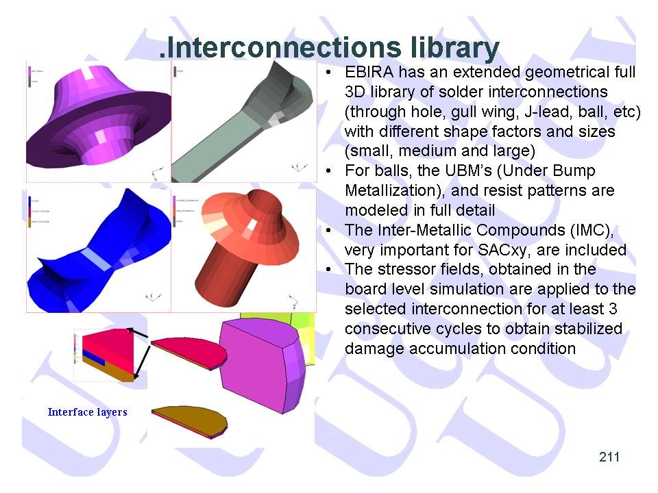
- Interconnection library
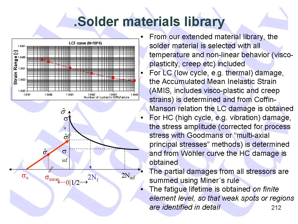
- Solder materials library
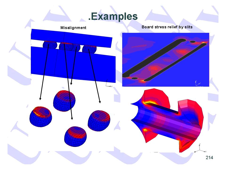
- Examples 1
- Examples 2
Udy started commercial thermal management and reliability projects in 1990 under the brand name EBIRA and acquired over the years a world-class know how in this area. Our expertise is continuously updated and expanded in close collaboration with our key customers and by using the latest international conference data from EUROSIME and SEMI-THERM
As is generally known, failure of one component or interconnection of the PCB/PBA causes total board failure and can imply important safety and financial issues (e.g. Microsoft’s X-box)
Physical testing, even accelerated, is tedious, costly and time consuming, and the relation with reality is not clear. Although physical testing never can be substituted, pre-screening by simulations to relieve test appliances, can also be an attractive alternative
Udy uses a stepwise approach going from global (cabinet, PCB) to local (component and/or interconnection) models. This reduces the model complexity and calculation times considerably. The cabinet step can be omitted if only the standard test procedures are to be imposed on the PCB/PBA. Note that also hygral (moisture) effects are integrated, if necessary
- Thermal environment and cabinet, including natural, forced and radiation cooling, is modeled with CFD (Computational Fluid Dynamics)
- The thermal field is mapped and interpolated on the PCB/PBA and can be time dependent. This is important during warming-up. In this way, the thermo-mechanical interaction between the PCB and its embedded electronics is accurately taken into account
- The 2 previous steps are only needed for "real-life" simulations in which the real thermal boundary conditions are taken into account. If only a standard (virtual) tests is required, the thermal boundary conditions are directly applied at the PCB/PBA model, together with the mechanical boundary conditions
EBIRA Capabilities
- The board can have thousands of components and or interconnections
- Substrates: FR2, FR4, multi layer, foil, ceramics (AL2O3, AlN), glass, ...
- Including anisotropic material properties such as CTEz
- Technologies: wire, SMD, lead frame, BGA, connectors, RoHS compliant, etc
- Solder materials: Eutectic, Pb-free (SAC105 and SAC305), Indalloy150 (81Pb10In). Complete material models including temperature effects, visco-plasticty and creep
- The board can be subjected to stressors such as shock and vibration, cycling temperature and/or power and humidity
- Single-stressor virtual tests:
- Bending test
- TCT/TST Temperature Cycling/Shock Test
- PCT/PST Power Cycling/Shock Test
- CT Humidity Cycling Test
- VCT/VST Cycling/Shock test
- Random Vibration PSD Analysis
- PCB’s are often subjected to dynamical loads with uncorrelated frequencies and amplitudes. These loads cannot be simulated via normal frequency or transient analysis because of their statistical nature. They can only simulated adequately via Power Spectrum Density (PSD)
- HS Hot storage
- Multi-stressor virtual tests
- P+TCT Power + Temperature Cycling Test
- HALT Highly Accelerated Lifetime Test (6 DOF vibration)
- HASS Highly Accelerated Stress Screening
- MEOST Multi Environment Over Stress Test
- "Real-life" virtual test
- To be specified by end-user for the real operating condition, e.g. airplane-flight
- Drop, impact virtual tests
- Over-molding, potting virtual tests (e.g. brake sensor, lamp ballast)
- Development of new cooling concepts (heatsinks, backplates, microchannels, etc.)
- MTBF and Weibull analysis
- Interface with E-CAD tools (Mentor Graphics, Dip Trace, Eagle etc.)
- Design Rules, Best Practices and Design-for-Manufactung (DFMA)
See below for a short description and some examples from our portfolio
 |
| top |
 |
| top |
 |
| top |
 |
| top |
 |
| top |
 |
| top |
 |
| top |
 |
| top |
 |
| top |
 |
| top |
Many more are available. Please contact us for examples with more affinity to Your needs